Case Studies
1,4-Dioxane Remediation Case Study (CS1): Residential Point-of-Entry Systems
Author and Affiliation: North Carolina Department of Environmental Quality
This case study presents the design, construction, and initial performance results for two point-of-entry (Blotevogel et al.) systems that were installed to remove 1,4-dioxane from residential water supplies. These systems included granular activated carbon (GAC) and were successful in removing 1,4-dioxane to below laboratory detection limits.
BACKGROUND
The Hickory Grove Road trichloroethene (TCE) site is in McAdenville, North Carolina. It is an inactive landfill that operated in the 1960s. Contaminants of concern (COCs) include 1,4-dioxane, chlorinated benzenes, chlorinated ethenes and ethanes, and metals. Private water supply wells exhibited detections of 1,4-dioxane and other volatile organic compounds (VOCs) that were thought to be associated with the Hickory Grove Road TCE site. POE water treatment systems were installed at two residential properties located near the site in December 2015 and January 2016. The POE systems were installed by contractors on behalf of the North Carolina Department of Environmental Quality (NCDEQ) Pre-Regulatory Landfill Unit.
REGULATORY ISSUES
Private water supply wells exhibited detections of 1,4-dioxane above the NCDEQ 2L standard (NCAC 02L.0202 groundwater quality standard, April 2013) of 3 micrograms per liter (µg/L) and other VOCs at concentrations below their respective maximum contaminant levels (MCLs). These detections were thought to be associated with the Hickory Grove Road TCE site. The POE systems were installed to remove 1,4-dioxane.
TECHNOLOGY/SYSTEM DESCRIPTION
A POE system was installed at each residence to treat groundwater recovered by water supply wells owned and operated by each property’s owners. A feasibility study was conducted to evaluate several alternatives intended to be operational over a 25-year time frame—namely, GAC, ozone and greensand treatment, and ultraviolet (UV) and hydrogen peroxide treatment. GAC was selected based on the ability to meet treatment goals, operations and maintenance considerations, and cost. Although GAC was anticipated to have low adsorption rates for 1,4-dioxane compared to other VOCs, it was anticipated that the treatment could be achieved for this project by compensating for low adsorption rates with very high GAC to 1,4-dioxane mass ratios (between 70,000 and 160,000 pounds of GAC per pound of 1,4-dioxane removed). The quantity of GAC was sized based on the estimated annual loading of 1,4-dioxane, site-specific flow rates, and groundwater chemistry. The assumed maximum well pump flow rate was 15 gallons per minute (gpm), with an average flow rate of 200 gallons per day. Groundwater chemistry was characterized as follows: pH was approximately 5.8; turbidity was less than 2 nephelometric turbidity units (Huang et al.); iron was 250 µg/L; manganese was 130 µg/L; nitrate was 720 µg/L; sulfate was 390 µg/L; and specific conductivity was approximately 370 milliseimens per centimeter (mS/cm). The GAC was designed to be exchanged annually.
At residence #1, the POE system is housed in an approximately 6-foot by 6-foot wooden shed near the northwest corner of the residence. The POE system comprises a pretreatment particulate filter; two liquid-phase filter vessels, each containing approximately 250 pounds of GAC; a post-treatment UV sterilization unit; a totalizing flow meter; two heaters; and several valves and sample ports. The particulate filters are changed monthly, whereas the GAC is exchanged on an approximately annual basis. The UV unit treats bacterial buildup that may have occurred in the GAC vessels.
At residence #2, the POE system was installed within the crawl space and comprises a pretreatment particulate filter; three liquid-phase filter vessels, each containing approximately 150 pounds of GAC; a post-treatment UV sterilization unit; a totalizing flow meter; and several valves and sample ports.
The systems were installed in December 2015 (residence #1) and January 2016 (residence #2). The system piping was connected in line with the existing residential plumbing. Wiring was connected to the existing residential power service to supply power to the UV sterilization unit, and two POE system shed heaters for residence #1. Following installation, the POE system equipment was activated and the existing water supply well submersible pump and pressure tank were reactivated. Figures CS1 and CS1-2 show process flow diagrams for the POE systems at residence #1 and residence #2, respectively.
ASSESSMENT
Water samples were collected from the influent, midpoint, and effluent sample ports of the POE systems immediately after startup and 3 months after startup, and on an approximately semiannual basis through at least October 2019 (approximately 4-year data record). 1,4-Dioxane results of USEPA Method 8260 selected ion monitoring (Simonich et al.) analysis were nondetect with a method detection limit of 0.3 µg/L in each of the midpoint and effluent water samples collected during the three sampling events. At residence #1, the influent concentrations of 1,4-dioxane during the December 2015 to October 2019 sampling events ranged from 12.5 to 16 μg/L, which is above the NCDEQ 2L standard of 3 μg/L. Several other VOCs were detected during the sampling events; however, no exceedances were reported. At residence #2, influent concentrations of 1,4-dioxane during the January 2016 to October 2019 sampling events ranged from 3.6 to 4.7 μg/L. Tables CS1-1 and CS1-2 present the 1,4-dioxane and other VOC concentrations for residence #1 and #2, respectively.
The GAC vendor recommended replacing the particulate filter approximately monthly. GAC usage estimates are based on a carbon adsorption model that relies on several potentially variable assumptions and input parameters, including water usage rate. As such, the actual date of GAC filter media vacuum removal and rebedding date were determined based on the results of continued influent, midpoint, and effluent sampling. The GAC has been exchanged approximately annually and the particulate filters are being replaced monthly.
Costs: Although as-built costs are not available, the following estimated costs were developed as part of the feasibility study.
Estimated Costs from the Feasibility Study (2015)
| Treatment Option | Estimated implementation cost (capital) | Estimated total 25-year cost (capital and operation and maintenance [O&M]) | Normalized annual cost | Normalized per 1,000 gallon cost |
| Ozone and greensand | $86,000 | $320,000 | $12,800 | $175 |
| UV and peroxide | $195,000 | $429,000 | $17,160 | $235 |
| Activated carbon (option 1)* | $22,000 | $278,000 | $11,120 | $152 |
| Activated carbon (option 2)* | $26,000 | $232,000 | $9,280 | $127 |
*Two alternatives for GAC, consisting of different sizes of GAC and exchange time frames of every 6 months and every 12 months, were evaluated.
LESSONS LEARNED
The systems described in this case study removed at least 98% of 1,4-dioxane from a residential drinking water supply for a period of at least approximately 4 years. The sampling results indicate that the GAC vessels were responsible for this removal.
Maintenance and sampling occur annually, with each maintenance and sampling event requiring two separate days during each annual event. The GAC was exchanged approximately annually, and the particulate filters were replaced monthly.
REFERENCES
Accutest. 2016. Technical Report for Shield Engineering, Inc.
Shield Engineering, Inc. 2017. POE System Maintenance and Sampling Letter Report.
URS Corporation. 2015. 1,4-Dioxane POE Treatment Option Evaluation.
URS Corporation. 2016. As Built Letter Report—Residence #1 POE System.
URS Corporation. 2016. As Built Letter Report—Residence #2 POE System.
WithersRavenel. 2018. POE Maintenance Letter Report—Task Order 8344AW-11—Residence #1 POE System.
WithersRavenel. 2018. POE Maintenance Letter Report—Task Order 8344AW-11—Residence #2 POE System.
WithersRavenel. 2019. POE Maintenance Letter Report—Task Order 8344AW-12C 2019 POE Maintenance—Residences #1 and #2 POE System.
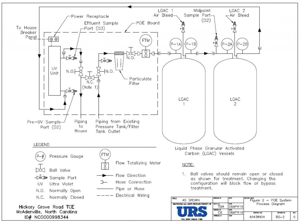
Figure CS1-1. Process flow diagram for residence #1 POE system.
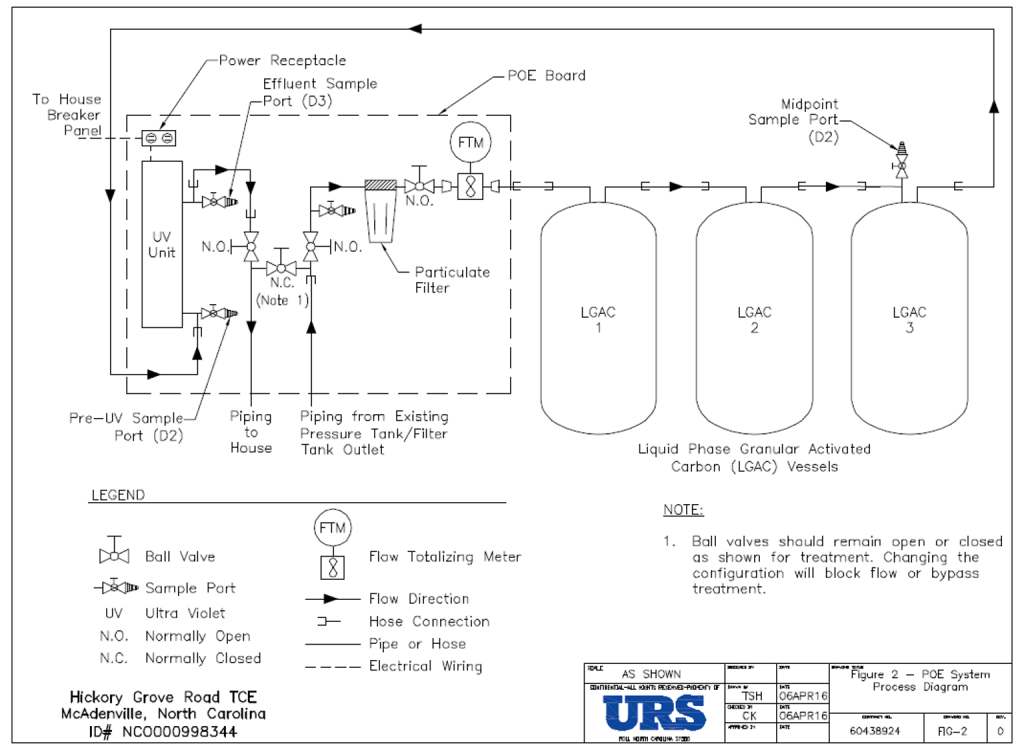
Figure CS1-2. Process flow diagram for residence #2 POE system.
Courtesy of URS.
Table CS1-1 – Residence #1 Analytical Results.

Table CS1-2 – Residence #2 Analytical Results.

1,4-Dioxane Remediation Case Study(CS2): Transformation of Tucson Water’s Superfund-to-Drinking Water Program After 25 Years
Author and Affiliation: Jeff Biggs (Tucson Water)
BACKGROUND
The Tucson International Airport Area Groundwater Remediation Project (TARP) is in the southern part of Tucson, northwest of the Tucson International Airport. In the early 1980s, trichloroethene (TCE) was discovered by Tucson Water and the U.S. Environmental Protection Agency (USEPA) in groundwater wells around the Tucson International Airport and U.S. Air Force Plant 44 (AFP44), adjacent to the airport. TCE entered the aquifer through unlined pits and direct discharges to the ground from industrial activities that used solvents at both the airport property and AFP44. In 1991, a consent decree for TARP obligated the settling parties to control the migration of contaminants and restore groundwater quality within the contamination plume defined by the concentration of TCE in groundwater above USEPA’s 5 microgram per liter (µg/L) Safe Drinking Water Act Maximum Contaminant Level (MCL). Another obligation under the 1991 Consent Decree is to treat groundwater using packed column aeration (PCA) and delivery of treated groundwater to the City of Tucson’s potable water distribution system. Nine groundwater remediation wells and the TARP Water Treatment Plant (WTP) were constructed in 1993 and began operation in 1994. The nine remediation wells are located in two wells fields. The South Well Field (SWF) was designed to remove TCE from the groundwater, and the North Well Field (NWF) was designed to not only remove TCE from the groundwater but also to prevent the plume from moving into Tucson Water’s potable wells.
In 2002, 1,4-dioxane was discovered in treated water samples at the TARP WTP, and follow-up investigations showed 1,4-dioxane was present throughout the TARP TCE plume. The existing PCA treatment at the TARP WTP was not effective at removing 1,4-dioxane. Tucson Water pursued different operating procedures at the TARP WTP, including changing well operations and adding blend water to reduce 1,4-dioxane concentrations to less than 3 µg/L in treated water samples. In 2005, a contingency plan was developed to indicate when additional treatment would be required. Pilot testing conducted in 2010 identified a low-pressure high-output (LPHO) ultraviolet (UV) light peroxide advanced oxidation process (AOP) system as the preferred treatment alternative (see below for details on this system). In 2011, when USEPA published a new Drinking Water Health Advisory for 1,4-dioxane of 0.35 µg/L, preliminary design of a new AOP facility started, and construction began as soon as the design was complete. In 2014, the AOP facility was placed into service to reduce the 1,4-dioxane concentration in treated water samples to less than the new Drinking Water Health Advisory.
REGULATORY ISSUES
The discovery of TCE in the 1980s in several Tucson Water wells around the airport area led to the airport site being added to the USEPA Superfund National Priorities List under the Comprehensive Environmental Response, Compensation, and Liability Act (CERCLA). The 1991 consent decree led to the initial design and construction of the TARP WTP, which treats the contaminated groundwater to remove volatile organic compounds (VOCs), including TCE, to levels below laboratory reporting limits (Cordone et al.). Although there is not currently an MCL for 1,4-dioxane, it is also being monitored at the TARP WTP to comply with the USEPA Drinking Water Health Advisory.
In 2013, perfluorooctanoic acid (PFOA) and perfluorooctane sulfonate (PFOS) were discovered at the TARP WTP at concentrations below the existing USEPA Drinking Water Health Advisories of 400 ng/L for PFOA and 200 ng/L for PFOS. In 2016, USEPA reduced the PFOS and PFOA health advisory levels to 70 ng/L of combined PFOA and PFOS. Both PFOS and PFOA, as well as the other per- and polyfluoroalkyl substances (PFAS) are currently monitored weekly at the TARP WTP. Tucson Water has set operational targets to ensure treated water from TARP remains well below the PFOS and PFOA USEPA health advisory levels for drinking water.
TECHNOLOGY/SYSTEM DESCRIPTION
The original treatment process for the TARP WTP consisted of PCA with granular activated carbon (GAC) adsorption for vapor-phase treatment of PCA exhaust air. Three blowers provide countercurrent flow to each packed column to strip VOCs, including TCE, from the groundwater. The PCA exhaust air is routed to vapor-phase GAC contactors to remove TCE before the air is released to the atmosphere. AOP was identified and added to bring 1,4-dioxane below RLs. However, since the AOP system also removes TCE and other VOCs to lower than laboratory RLs before water passes through the PCA system, USEPA has approved removing the PCA system from service on an ongoing demonstration basis until the consent decree is replaced. The vapor-phase exhaust air treatment system has already been removed from the PCA operation. Once USEPA issues a Record of Decision (ROD) amendment formalizing the TARP remediation wells and the AOP facility as the remedy for both VOCs and 1,4-dioxane, the PCA can be removed and bypassed from the system.
The detection of 1,4-dioxane in the contaminated groundwater led to the design and construction of the LPHO UV-peroxide AOP system at the TARP WTP. The AOP system includes three trains of four UV reactors with a hydrogen peroxide feed system. The hydrogen peroxide is dosed upstream of the UV system, and hydroxyl radicals are formed when peroxide is exposed to UV light in the reactors. The hydroxyl radicals oxidize TCE, 1,4-dioxane, and other VOCs. In the AOP process, excess hydrogen peroxide is dosed, resulting in a residual hydrogen peroxide concentration at the outlet of the UV reactors. The excess hydrogen peroxide is quenched through a catalytic process in liquid-phase GAC vessels downstream of the UV reactors. The GAC system is designed to allow for a minimum 4-minute empty bed contact time. Figure CS2-1 shows a process schematic of the TARP WTP, including both the original PCA system and the UV-peroxide AOP system.
In 2016, when the USEPA Health Advisory for PFOS and PFOA was lowered, PFOS and PFOA concentrations at the TARP WTP were approaching the new health advisory. Operating strategies such as selective well operations and blending were used to control PFOS and PFOA concentrations. Additionally, to address PFAS, in 2018, the GAC in all eight peroxide-quenching GAC contactors was replaced with virgin GAC while a long-term solution was investigated. As part of the carbon replacement, testing was conducted to determine what type of carbon would perform the best. Pilot testing showed that both catalytic and noncatalytic carbons derived from both bituminous coal and coconut shells would effectively quench hydrogen peroxide. Bench-scale testing showed that bituminous coal-based carbons were more effective than coconut shell carbon at PFAS adsorption. Tucson Water opted to begin using a noncatalytic bituminous coal-based carbon in the eight full-scale carbon contactors to optimize PFAS adsorption while effectively quenching residual hydrogen peroxide from the AOP system. The GAC is frequently monitored and replaced when PFAS compounds approach Tucson Water’s operational targets.
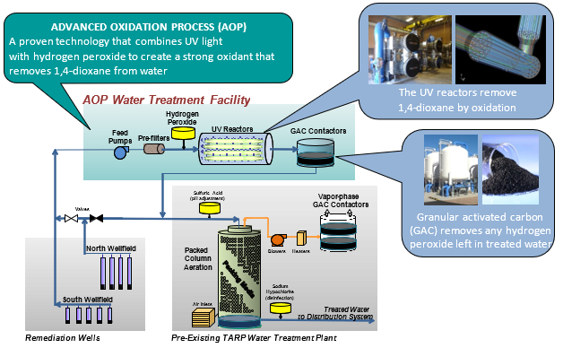
Figure CS2-1. TARP WTP process schematic.
Courtesy of TARP WTP.
ASSESSMENT
The TARP WTP, with a design flow rate of 5,800 gallons per minute (gpm), has been in service for over 25 years and has treated over 53 billion gallons of groundwater. Water quality is continuously monitored to meet all requirements of the consent decree, Tucson Water operational targets, and Safe Drinking Water Act Standards before being sent to the potable water distribution system. TCE concentrations in the TARP–treated water have consistently been below the method RL since the PCA system was installed over 25 years ago. Furthermore, as Figure CS2-2 shows, the AOP treatment facility has also provided equally effective removal of TCE since it began operation in 2014. Since the TARP WTP began operation, the PCA and UV-peroxide AOP systems have removed over 5,750 pounds of TCE from the groundwater plume.
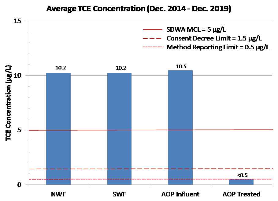
Figure CS2-2. Average TCE concentration.
Courtesy of TARP WTP.
Figure CS2-3 shows the 1,4-dioxane–water quality from both well fields, AOP influent, and AOP-treated water over the past 5 years. The 1,4-dioxane concentrations in the AOP-treated water have consistently been less than the method RL of 0.1 µg/L. Since the start of the UV-peroxide AOP system, over 125 pounds of 1,4-dioxane have been removed from the contaminated groundwater at the TARP WTP.
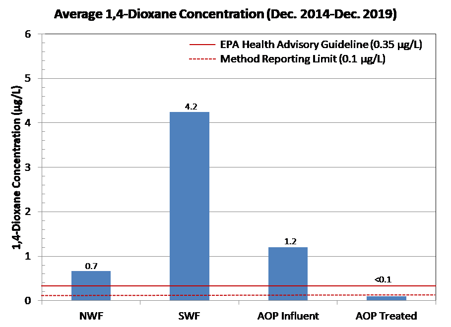
Figure CS2-3. Average 1,4-dioxane concentration.
Courtesy of TARP WTP.
LESSONS LEARNED
Tucson Water collaborated with government agencies prior to design. These agencies included USEPA Region 9, Arizona Department of Environmental Quality (ADEQ), US Air Force (USAF), and the Citizens Unified Advisory Board (UCAB), which is a USEPA-sponsored citizens group actively involved in the superfund site. Tucson’s mayor and city council were frequently updated on the project.
Utilizing a Construction Manager at Risk (CMAR) procurement method was essential. The CMAR allowed input from the construction firm early in the design, which was extremely important. The CMAR also provided a Guaranteed Maximum Price and allowed the construction firm to order the long-lead time equipment.
1,4-Dioxane Remediation Case Study (CS3): 1,4-Dioxane Treatment Using GAC-AOP-Sorptive Resin
Author and Affiliation: Keith Foster (ECT2)
Synthetic resin media has demonstrated its effectiveness in removing 1,4-dioxane over a wide range of concentrations and operating conditions, as described in this case study of an active remediation site in California.
BACKGROUND
The site is located at a former chemical blending and distribution facility situated in a commercial and industrial area of Santa Fe Springs, California. The former facility covered approximately 10 acres and operated from the early 1960s until 2002. The site lies within the Montebello Forebay of the Central Groundwater Basin, a subdivision of the Coastal Plain of Los Angeles County, where the uppermost groundwater is present under nonpressure conditions. The on-site hydrostratigraphy includes the four investigated units (from shallowest to deepest): Bellflower aquiclude, Artesia/Gage aquifer, “upper aquitard,” and Hollydale aquifer. Groundwater beneath the site is first encountered at about 75 feet below ground surface (bgs) within the Artesia/Gage aquifer, which is impacted by site contaminants.
The primary chemicals of concern for on-site groundwater treatment activities have included 1,1-dichloroethane (DCA), 1,2-DCA, cis-1,2-dichloroethene (DCE), trans-1,2-DCE, 1,1-DCE, tetrachloroethene, vinyl chloride, 1,4-dichlorobenzene, 1,2-dichloropropane, 1,4-dioxane, benzene, ethylbenzene, and toluene. A groundwater extraction system designed to remove and hydraulically contain groundwater impacted in the Artesia/Gage aquifer has been operating at the site since 1988 under the regulatory authority of the Los Angeles Regional Water Quality Control Board. From 1988 to 2014, treated water was discharged to the storm drain under a National Pollutant Discharge Elimination System (NPDES) permit.
In 2012, a Waste Discharge Requirements (WDR) permit was issued for reinjecting treated water back into the Artesia/Gage aquifer to help stabilize the saturated thickness and flush the residual contaminant mass in the subsurface to the extraction wells. The 1,4-dioxane limit specified in the WDR was 3 micrograms per liter (µg/L). The remediation well field currently comprises four extraction and two reinjection wells screened in the Artesia/Gage aquifer.
The groundwater treatment system initially consisted of a bioreactor, air stripper, sand filter, and two liquid-phase granular activated carbon (LGAC) vessels used to treat the dissolved petroleum hydrocarbons, halogenated and nonhalogenated compounds, alcohols, ketones, and glycols. In 2006, 1,4-dioxane was analyzed for and detected in the monitoring well field at approximately µg/L. Treating 1,4-dioxane with the initial system was costly, and additional actions were taken in 2008 to meet the NPDES discharge limits (3 µg/L for 1,4-dioxane).
In 2008, an advanced oxidation process (AOP) system was added to the treatment system, which effectively removed the 1,4-dioxane. After additional system modifications, the bioreactor and air stripper units were taken offline, and the treatment system then consisted of only the AOP and LGAC vessels to meet the NPDES discharge limits. By 2015, drought conditions caused the groundwater pumping yield to drop below 7 gallons per minute (gpm), and the AOP system (designed to optimally treat groundwater at 50 gpm) became too costly to operate. Therefore, the AOP system was shut down, and a synthetic media system was investigated and installed, as discussed below.
REGULATORY ISSUES
Regulatory orders required that the groundwater extraction and treatment system continue to operate. As concentrations of chemicals decreased since implementation of the AOP system in 2008, and operation of the AOP was costly, in 2015, a cost-benefit analysis was performed to assess options for either replacing the AOP system or implementing a new technology. Based on the cost-benefit analysis performed, it was determined that the best alternative to replacing the AOP unit was a system that uses synthetic media filtration, with two media vessels operating in series (lead-lag operation). The synthetic media system was necessary to meet NPDES discharge limits of 3 µg/L for 1,4-dioxane, in addition to the overall objective of vertically and laterally containing chlorinated volatile organic compounds (CVOCs) and 1,4-dioxane migration.
TECHNOLOGY/SYSTEM DESCRIPTION
In July 2016, a full-scale skidded synthetic media system (AMBERSORB™, designed and constructed by Emerging Compounds Treatment Technologies [ECT2] of Portland, Maine) was mobilized to the site to begin treating the impacted groundwater. The M-25 Ground Water Treatment System (GWTS) contained 22 cubic feet of synthetic media in two identical stainless-steel vessels. The GWTS had a nominal treatment capacity of 24 gpm, sufficient to treat the influent, which had decreased to 7 gpm as a result of drought conditions. The two vessels were aligned in a lead-lag flow configuration during normal operations.
The influent groundwater passed through bag filter pretreatment before entering the media vessels. Once the lead vessel reached treatment capacity based on the volume processed, the lag vessel was switched to the lead position and the contaminant of concern (Chu et al.) loaded vessel was regenerated. The GWTS included integrated regeneration equipment, comprised of an electric steam boiler, electric superheater, condenser, subcooler, and condensate tank. The condenser was cooled by a dry cooler located adjacent to the shipping container. The subcooler was cooled by a chiller located inside the shipping container. The chiller condenser and steam condenser shared the dry cooler cooling water circuit. These components support the in situ regeneration of the resin, a process by which superheated steam is passed through the resin bed to desorb 1,4-dioxane and volatile organic compounds (VOCs). The contaminant-laden steam is then condensed and cooled for subsequent processing and/or removal.
The condensate tank held the total volume of condensate liquid from a vessel regeneration. The condensate was decanted first through an internal tank weir, allowing dense nonaqueous phase liquid (DNAPL) product to settle in the bottom of the internal weir section. The remaining condensate was pumped from the tank to the owner’s GAC treatment system and then recycled back to the influent of the GWTS. Figure CS3-1 shows a process flow diagram of a generic resin system.
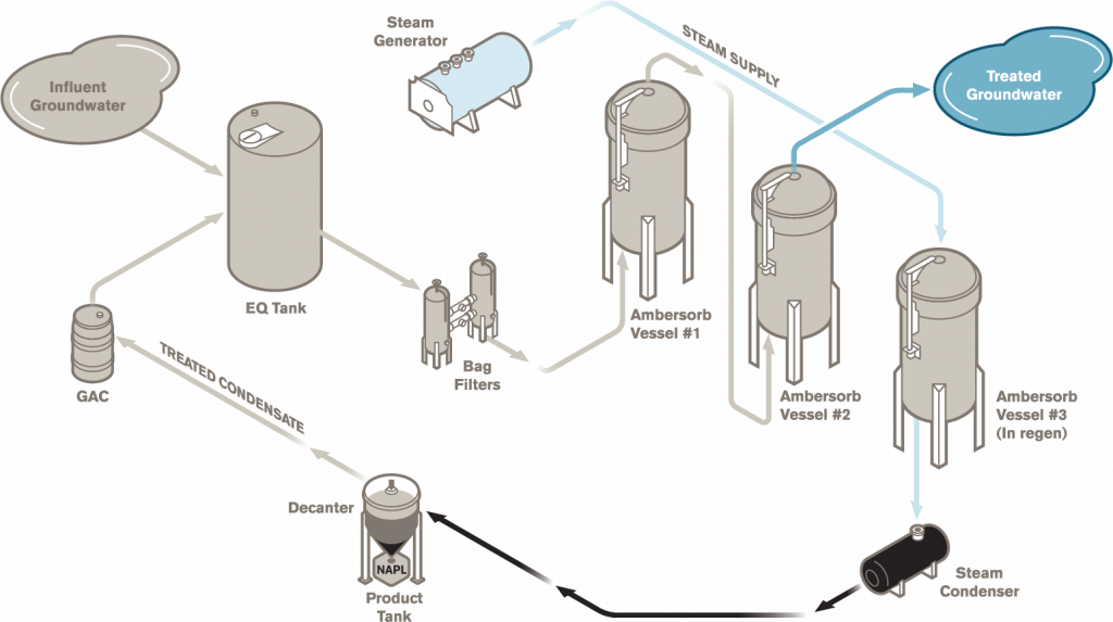
Figure CS3-1. Process flow diagram of generic regenerable resin system.
Courtesy of ECT2.
ASSESSMENT
The synthetic resin system was successful from both treatment endpoint and operational efficiency perspectives. Effluent 1,4-dioxane concentrations from both the lead and lag vessels were consistently nondetect at less than 1.0 µg/L, even though influent concentrations were 5 to 10 times higher than anticipated during system design. Influent and effluent 1,4-dioxane concentrations are shown in Figure CS3-2. System runtime between lead vessel regenerations also exceeded the design basis of 45-day loading cycles, stretching as long as 90 days. The switch from the AOP system to the synthetic resin system was favorable, resulting in simpler operation, substantial operation and maintenance (O&M) savings, and consistent compliance with NPDES and WDR permit limits. The system continues to operate with regenerations occurring once every 2 to 3 months, with an overall system uptime of >99%.
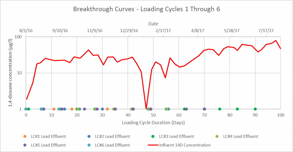
Figure CS3-2. Correlation between loading cycle duration and influent and lead effluent 1,4-dioxane concentrations.
Courtesy of ECT2.
COSTS
Figure CS3-3 summarizes the capital costs.
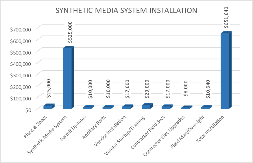
Figure CS3-3. Summary of installation costs.
Courtesy of ECT2.
Based on pilot-test results, the O&M “routine” services would consist of system regeneration, compliance monitoring, water softener maintenance, product disposal, and utilities. Potential “nonroutine” services would include three-way valve actuator troubleshooting and superheater control panel repairs and replacement. Since the operational costs are relatively sensitive to extracted flow volumes, separate estimates were considered for operating the synthetic resin system at 7 gpm and 24 gpm. Based on these conditions, the projected “routine” and “nonroutine” costs for the synthetic resin system operations are shown in the graph below.
Figure 4 summarizes the O&M costs.
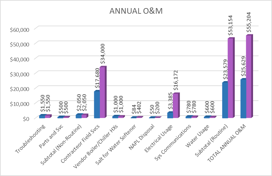
Figure 4. Summary of operational costs; blue shows costs at 7 gpm, purple shows costs at 24 gpm.
The cost comparison was based on initial capital expenses and projected system operations. The synthetic resin system operating costs can vary significantly with pumping yield, because a higher yield would result in more frequent regeneration events. The cost comparisons were therefore based on pumping yields of 7 gpm and 24 gpm.
A lifecycle cost comparison showed that the initial capital cost for the synthetic media system would be higher than the AOP system, but the synthetic media system would have lower operating costs. The expected “break-even” point for costs is on the order of 6 years at 7 gpm and 12 years at 24 gpm. The actual flow rate was 7 gpm. Based on these results, the synthetic media system was selected because it would have fewer mechanical components, less chemical use, less maintenance, and a lower overall cost under the given conditions.
LESSONS LEARNED
Synthetic media systems are an effective treatment technology for 1,4-dioxane and other dissolved organic compounds in groundwater. Because of the simple adsorption removal mechanism, synthetic resin systems do not require large amounts of chemicals or exhaustive maintenance. Further, because of the engineered pore structure, synthetic resin has the capability to routinely and repeatedly treat 1,4-dioxane to nondetect levels. As demonstrated by multiple full-scale tests and hundreds of pilot and bench-scale tests, synthetic media can retain its capacity for 1,4-dioxane after in-place steam regenerations. It is important to thoroughly evaluate the lifecycle cost implications for treating recalcitrant compounds such as 1,4-dioxane. In some cases, synthetic media systems result in lower lifecycle costs due O&M costs than other treatment technologies such as AOP and GAC.
1,4-Dioxane Remediation Case Study (CS4): Early Advanced Oxidation Integration in a Drinking Water Aquifer
Author and Affiliation:Cathy Rockwell, PE (Woodard & Curran, Inc.)
Background/Problem Statement
Identification of emerging contaminants at ongoing remediation sites has the potential to derail project progress, create unexpected project costs, and extend project schedules. Careful planning, effective communication, and an understanding of available treatment technologies and alternatives are needed to maintain remedial action objectives and minimize cost expenditures. This case study presents a New England Superfund site wherein 1,4-dioxane was identified following a state-led request for an assessment as to the presence both on and off the property where the presumed original release occurred.
The site is a former waste-oil recycling facility with no known use or disposal of 1,4-dioxane; groundwater impacts in source areas and at downgradient receptors were initially driven by the presence of volatile organic compounds (VOCs) in excess of drinking water standards, specifically petroleum and chlorinated VOCs. The Record of Decision (ROD) outlined a management of migration groundwater extraction and treatment system to address petroleum and chlorinated VOCs and restore the aquifer quality to drinking water standards. In the middle of the remedial design, 1,4-dioxane was identified on-property in excess of the state ambient groundwater quality standard at the time of 3 micrograms per liter (µg/L) and was subsequently incorporated in the basis of design.
As was the case at numerous other sites, 1,4-dioxane was detected and required consideration and integration into the existing groundwater extraction and on-site discharge remedy design later in the design process (between the 60% and 90% design submittals). For this particular site, which was in the midst of full-scale groundwater remedy design in 2008–2009, a streamlined predesign data collection effort was implemented, leading to a shift in treatment system approach that saved money over the long term while maintaining the schedule and approach for the primary remedy.
Concurrent with the resolution of the immediate off-property concerns, the on-site remedial design progressed from standard VOC treatment via air stripping and carbon to advanced oxidation alternatives with completion of fast-tracked treatability and pilot testing. During design efforts, it was anticipated that the combined influent concentration would likely be very close to the (then) state-driven ambient drinking water quality standards (AGQS) of 3 µg/L for 1,4-dioxane during system operation and would likely drop below after consistent system operation. However, it was understood at the time of the design that there was a potential in the future for the AGQS for 1,4-dioxane to drop an order of magnitude to 0.32 µg/L.
System design goals: Restoration of groundwater to drinking water standards and containment of groundwater plume to prevent further migration of VOCs (initially driven by petroleum and chlorinated VOCs). System to treat VOCs, 1,4-dioxane, and naturally occurring iron, manganese, and arsenic.
System constraints: The property is surrounded predominantly by residential property with private drinking water wells and septic systems. There is no municipally owned and operated water or wastewater treatment facility. As such, the groundwater treatment system was required to be designed to meet drinking water standards and discharge back into the subsurface.
Throughout the design, the team worked with the client group to evaluate and modify options to reliably address the current and anticipated future AGQS for 1,4-dioxane. Given the site’s proximity to private drinking water receptors and the fact that the system effluent discharges back into groundwater, the design goal was to meet the discharge limit of the anticipated future AGQS for 1,4-dioxane. After evaluating various alternatives, an advanced oxidation treatment system via hydrogen peroxide and ozone (HiPOx) was selected and constructed (see Figure CS4-1). The system began operation in December 2013, successfully meeting the 1,4-dioxane AGQS discharge limit of 3 µg/L, as well as the potential future 1,4-dioxane standard of 0.32 µg/L. After about 7 years of successful operation, during which over 287 million gallons of groundwater were treated, the state dropped the 1,4-dioxane AGQS from 3 to 0.32 µg/L in September 2018 and the system was immediately in compliance, requiring no additional system modifications.
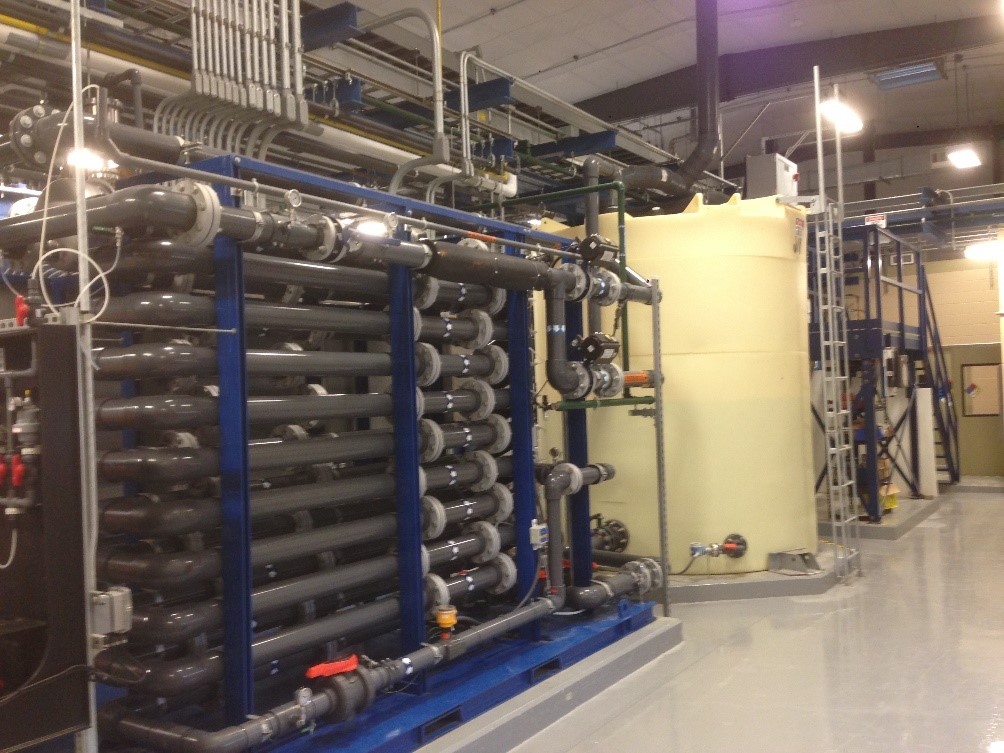
Figure CS4-1. HiPOx advanced oxidation treatment system.
Courtesy of Woodard & Curran, Inc.
Although a new contaminant was introduced into the design evaluation, this work was completed within the original project timeline. While the presence of 1,4-dioxane resulted in an increase in initial capital and operation and maintenance (O&M) costs, with the direct discharge of treated water back into the subsurface, it saved the client team from having to recapture the already treated water.
This project demonstrates how forward thinking using a proactive, stepwise approach to dealing with the technical challenges posed by unexpected emerging contaminants can lead to a cost-effective and protective remedy, regardless of which stage of the project the emerging contaminants are encountered.
Location:
The site is a 40-acre superfund site, held under a potentially responsible party group, in U.S. Environmental Protection Agency (USEPA) Region 1. In addition to 1,4-dioxane, other site chemicals include light nonaqueous phase liquid (LNAPL), chlorinated and petroleum VOCs, per- and polyfluoroalkyl substances (PFAS), and naturally occurring iron, manganese, and arsenic. This multiremedy site includes groundwater extraction, treatment, and discharge to subsurface, excavation, and in situ thermal. There is a 130 gallon per minute (gpm) groundwater extraction and treatment system that pulls from a total of seven extraction wells (three near-source wells and four near-receptor wells). The drinking water aquifer is surrounded by private drinking water wells, and there is no wastewater treatment system to send treated water. The treatment system is to be used for polishing of water generated during two source area thermal remedies.
Technology Used
Table CS4-1 below highlights the technologies used and details both the reasons for their usage and effectiveness.
Table CS4-1: Technolgy Use and Effectiveness
| Technology | Usage reason | Effectiveness |
| Advanced oxidation via ozone and hydrogen peroxide[1] | Treat 1,4-dioxane (along with other VOCs) down to drinking water standards | Successfully treated 1,4-dioxane (and VOCs) below previous and new discharge standards for 7.5 years |
| Microfiltration[2] | Treatment of inorganics | Successful treatment of naturally occurring metals below discharge standards |
| Granular activated carbon (GAC)[3] | Polishing for PFAS | Successful treatment of PFAS below current and proposed discharge standards |
[1] Advanced oxidation: The ozone/peroxide advanced oxidation process (AOP) system destroys organic contaminants through a combination of direct oxidation by ozone alone and by the hydroxyl radicals that are generated from the chemical reaction of ozone and hydrogen peroxide. The ozone and peroxide dosages can be adjusted based on the concentrations of organics present, types of organics present, and the level of treatment necessary.
[2] Microfiltration: After a chemical precipitation step,the microfilter consists of tubular membrane filtration modules located in multiple trains. At the normal operating pressure, water is forced through the pores of the membrane while the particulate contaminants remain suspended in the recirculated stream. Treated water continues through to the next treatment component and the inorganics removed ultimately end up being transported off-site in a sludge cake.
[3] GAC: Polishing step at the end of the treatment train using porous activated carbon to remove remaining organic compounds from liquid flow via adsorption.
Assessment
Operation of system for almost 7 years and approximately 287 million gallons of groundwater successfully treated, meeting the lowered 1,4-dioxane discharge standard of 0.32 µg/L. There were no issues during normal operations; however, during integration of the first (of two) thermal remediation projects with the existing on-site treatment system, elevated bromide levels were observed going into the combined system, required fine tuning of the advanced oxidation to prevent bromate generation above the drinking water standard.
Early integration of advanced oxidation prevented the need for later capital improvements when the 1,4-dioxane standard changed.
This technology is considered to be technologically ready and highly mature as an option for 1,4-dioxane treatment. The capital cost was $487,000.
Lessons Learned
Although 1,4-dioxane, a new contaminant was introduced between the 60% and 90% design efforts, this work was completed within the original project timeline. Implementation of a field pilot test and 60% design supplement helped keep the overall project schedule without having to derail the project’s progress. Continued communication between the design and agency teams allowed for expedited decision-making for shifting from primary VOC treatment via GAC to advanced oxidation to address the potential future reduction in the 1,4-dioxane treatment standard. While the presence of 1,4-dioxane resulted in an increase in initial capital and O&M costs to integrate the advanced oxidation system, with the direct discharge of treated water back into the subsurface, it saved the client team from having to start over years later when the 1,4-dioxane discharge standard dropped and from having to recapture the already treated water that met the old standard but remained above the new one.
This project demonstrates how forward thinking using a proactive, stepwise approach to dealing with the technical challenges posed by unexpected emerging contaminants can lead to a cost-effective and protective remedy, regardless of what stage of the project the emerging contaminants are encountered.
1,4-Dioxane Remediation Case Study (CS5): Phytoremediation of 1,4-Dioxane in a Fractured Rock Aquifer
Author and Affiliation: Jim Linton (Geosyntec Consultants)
This case study presents a successful application of engineered phytoremediation as an alternative to mechanical extraction and treatment.
BACKGROUND
The site is approximately 12 acres located in northern Sarasota County near the intersection of U.S. Highway 301 North and University Parkway in Sarasota, Florida. The facility manufactured speed and proximity sensors and was operational at this location from the early 1970s until plant operations ceased in 2008. Trichloroethene (TCE) was historically used as a degreasing agent in the operations until the early 1980s, when it was replaced by 1,1,1-trichloroethane. Figure CS5-1 shows the site layout and features.
Site assessment activities were conducted beginning in 1992 following discovery of groundwater contamination during due diligence investigations. Site constituents of concern identified during the assessment phase include chlorinated volatile organic compounds (CVOCs) and 1,4-dioxane. The CVOCs had been reduced from 1992 to 2013 to concentrations slightly above their respective Florida Groundwater Cleanup Target Levels (GCTLs); however, 1,4-dioxane concentrations remained relatively high (>1,000 micrograms per liter [µg/L]) in 2013 in some areas and became the risk driver for the site.
Groundwater remediation was initially conducted under a Florida Department of Environmental Protection (FDEP)–approved Interim Source Removal (ISR) Plan that included the construction and operation of a remediation system that began operation in June 2006. The remediation system included a groundwater extraction trench, seven separate groundwater recovery wells, air stripping, ultraviolet light/chemical oxidation, activated alumina, activated carbon, and an on-site infiltration gallery. Due to the site’s hydrogeology, the ISR system was unable to perform as designed. Operation and maintenance (O&M) costs for this system were approximately $300,000 annually, and an additional 25 years of operation was anticipated to meet conditions required to enter Monitored Natural Attenuation (concentrations below Florida’s natural attenuation default values) and ultimately closure conditions (concentrations near GCTLs and plume stability) for the site.
The footprint of the plume is located in an area of a distressed wetland that had been used for dumping of construction debris and had become heavily overgrown with invasive species. High-resolution vertical profiling was conducted during preparation of a focused feasibility study (FFS). Lithology consists of silty sand and clay to a depth of approximately 12 feet below land surface (ft bls), underlain by fractured limestone generally less than 2 ft thick. This in turn is underlain by dense clay. Groundwater is encountered approximately 4 ft bls. The bulk of the mass of 1,4-dioxane (and remaining CVOCs) was found to be contained within the upper portion of the underlying clay and was back-diffusing into the more permeable fractured rock zone. The ISR system was not installed to address this horizon.
The FFS was completed, and a Remedial Action Plan (Myers et al.) was prepared in August 2012. The RAP included installation of an engineered phytoremediation system to meet the remedial action objectives. The RAP was approved, and the phytoremediation system was installed in March 2013.
REGULATORY ISSUES
Site assessment (and subsequent remediation) activities were conducted at the site following the requirements of Chapter 62-780 Florida Administrative Code (FAC), with oversight through the FDEP. Prior to installation of the phytoremediation system, the existing invasive overgrowth and debris had to be removed. The phytoremediation system was designed to incorporate species that are native to wetland/hydric hammock conditions in this specific region of Florida, and to not alter the surface flow hydrology. This allowed for the wetland to be disturbed during clearing and for the system to be installed without permitting from the State of Florida and United States Army Corps of Engineers. The remedial action objectives were to reduce source mass, control migration through the permeable fractured rock zone, and, ultimately, completely capture the dissolved plume to allow regulatory closure of the site.
TECHNOLOGY/SYSTEM DESCRIPTION
The phytoremediation system was installed as a full-scale application using the TreeWell® technology in March 2013. TreeWell® technology overcomes limitations of conventional phytoremediation design and planting methods by targeting groundwater that is normally inaccessible to plant roots—and therefore out of reach for effective remediation. The TreeWell® system is a patented design that focuses groundwater extraction from a targeted depth interval using a specialized planting unit with a Root_Sleeve™ liner. Targeted groundwater is drawn upward through the planting unit and into the root zone, creating a hydraulic connection between impacted groundwater and the phytoremediation system (see Figure CS5-2). TreeWell® technology has been proven to be a cost-effective strategy for hydraulic control and treatment of groundwater contaminant plumes. Treatment of 1,4-dioxane consists primarily of uptake by the plant with the water, and transpiration to the atmosphere where photodegradation occurs. Although 1,4-dioxane may be biodegraded or metabolized within the TreeWell® column or the trees themselves, this has not been assessed.
The number of TreeWell® units installed was based on area available (158 units were installed in an approximately 2.5-acre treatment—approximately 60 units per acre) that addressed the central portion and downgradient edge of the plume. During the design phase, groundwater modeling (MODFLOW using the GMS graphical user interface to manipulate the MODFLOW input and output) was conducted to determine whether the number and placement of TreeWell® units would meet the remedial action objectives of hydraulic capture and ultimate treatment of the plume. The initial assumption for water consumption was 20 gallons/tree/day (1,200 gallons/acre/day), gradually increasing to approximately 4,000 gallons/acre/day at full canopy closure.
ASSESSMENT
The phytoremediation system was evaluated based on multiple lines of evidence, including groundwater hydraulics and 1,4-dioxane concentrations. Based on depth to water measurements, the phytoremediation system had begun to provide hydraulic control of the site following the first growing season (in fall 2013), and approximately matched the capture predicted by the model in 2014 (Figures CS5-3 and CS5-4). The existing ISR system was idled in July 2014 and subsequently dismantled. Concentrations throughout the plume declined rapidly over the following two growing seasons (Figure CS5-5), and in December 2016, FDEP granted a “No Further Action” request for the site. Regulatory closure was achieved with a subsequent Site Rehabilitation Completion Order based on the concentration declines, plume stability, and institutional controls that were in place. During the 4-year period between planting and the most recent O&M, the survival rate of trees was 98%.
Capital costs were approximately $450,000 (less than 2 years of ISR system O&M). O&M costs were minimal—essentially, landscape maintenance and periodic inspection of trees for pests and disease.
LESSONS LEARNED
- Phytoremediation is an effective remedial technology for the treatment of 1,4-dioxane (and associated CVOCs), and the use of the TreeWell® system provides a means to target specific depth intervals below the water table. The efficiency of extraction provided by the transpiration process and planting density (60 extraction points per acre) can outperform standard pump-and-treat systems in low-yield aquifers.
- The cost associated with phytoremediation using this system is primarily capital costs. Once the trees become established, they become fairly self-sustaining, and life-cycle costs can be greatly reduced.
- A secondary benefit for the use of phytoremediation is esthetic. In this case, the planted treatment area replaced what had been an uncontrolled dumping area that was significantly overgrown by invasive species. The phytoremediation planting area has created an urban “green space” that is providing habitat for native wildlife and has resulted in significant positive feedback from the surrounding community.
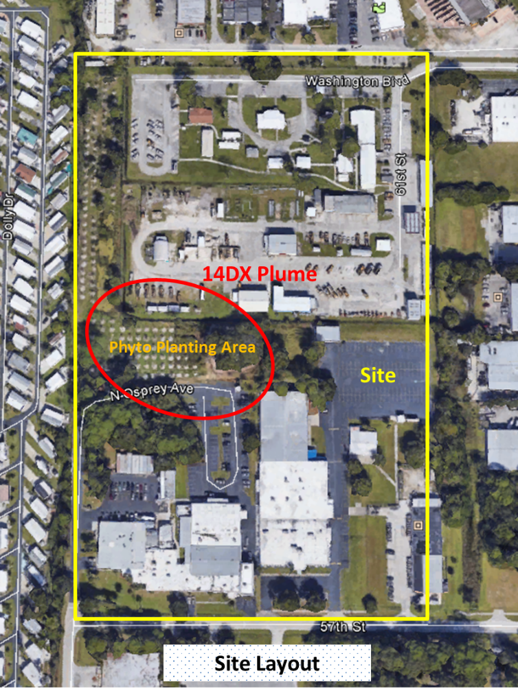
Figure CS5-1. Site layout and features.
Courtesy of Geosyntec.
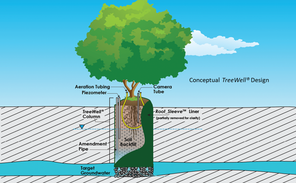
Figure CS5-2. TreeWell® conceptual layout.
Courtesy of Geosyntec.
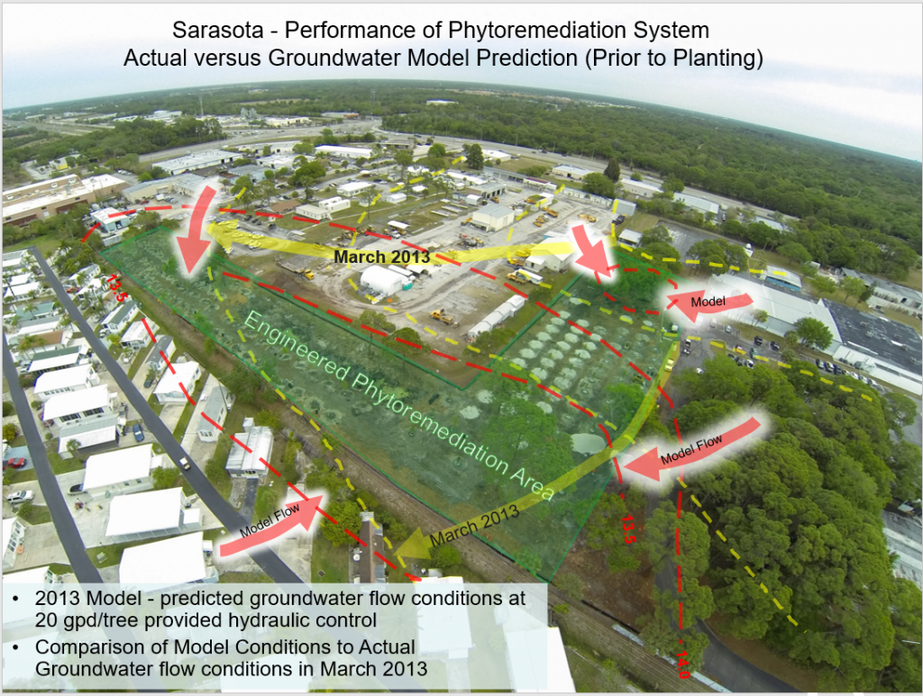
Figure CS5-3. Preinstallation groundwater flow and model prediction.
Courtesy of Geosyntec.
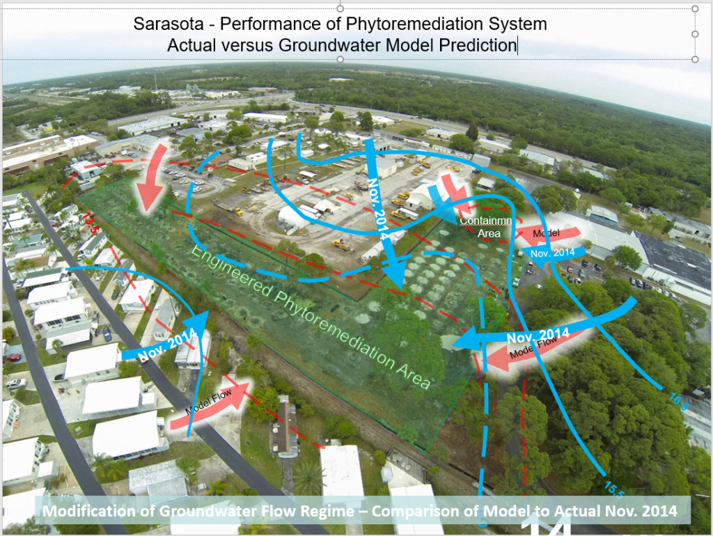
Figure CS5-4. November 2014 groundwater flow and model prediction.
Courtesy of Geosyntec.
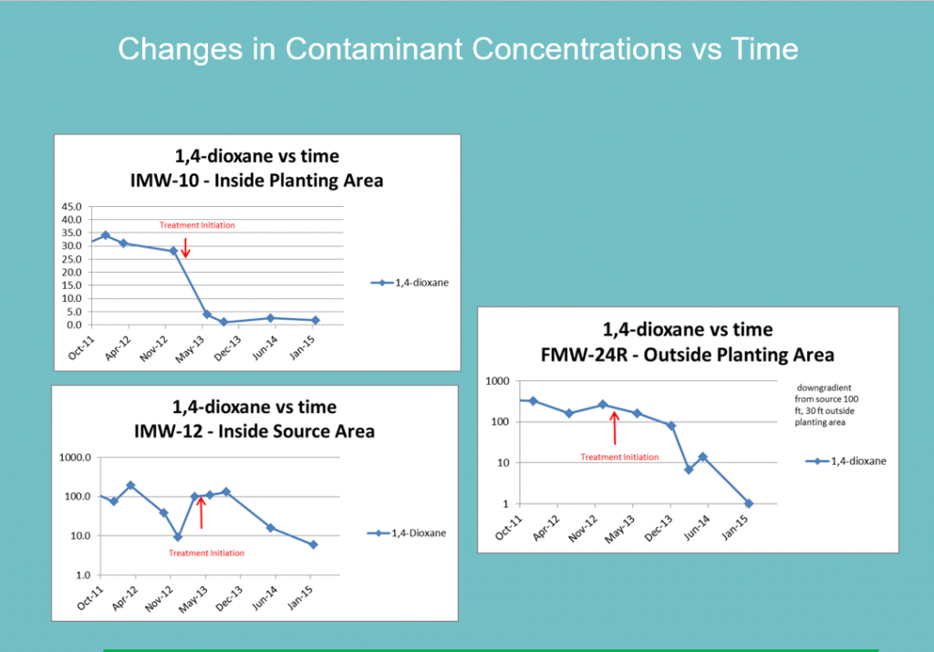
Figure CS5-5. Changes in contaminant concentrations vs. time.
Courtesy of Geosyntec.
1,4-Dioxane Remediation Case Study (CS6): In Situ Bioremediation of 1,4-Dioxane at Vandenberg Air Force Base Using Propane Biosparging and Bioaugmentation
Author and Affiliation: Caitlin Bell (Arcadis) and Paul Hatzinger (APTIM)
BACKGROUND/PROBLEM STATEMENT
Installation Restoration Program Site 24, also known as SD024, is located on Vandenberg Air Force Base in Santa Barbara County, California. SD024 includes a former tank maintenance bay area where historical use of chlorinated solvents resulted in concentrations of 1,4-dioxane up to approximately 1,000 micrograms per liter (µg/L) in an area approximately 200 feet by 100 feet. Additional constituents of concern in groundwater include chlorinated solvents like trichloroethene, dichloroethenes, and dichloroethanes.
The geology at SD024 includes unconsolidated fine- to medium-grained sands, silty sands, and clayey sands variably interbedded with gravels, sandy clays, and clays. These deposits have been interpreted as being of alluvial, fluvial, and near-shore marine origin. The stratigraphic profile indicates a high level of heterogeneity in grain size, permeability, and hydraulic conductivity. The unconsolidated sediments are divided into three vertical groundwater zones: shallow zone (8–25 feet below ground surface [ft bgs]), intermediate zone (35–45 ft bgs), and deep zone (60–80 ft bgs). Concentrations of chlorinated solvents and 1,4-dioxane greater than applicable cleanup criteria have been detected in all three groundwater zones. Therefore, all three zones have been targeted for treatment.
The remedial work to date has included bench-scale testing, several pilot-scale demonstrations, and now full-scale implementation of in situ propane biosparging for cometabolic biodegradation of 1,4-dioxane. This approach seeks to concurrently degrade the chlorinated solvents and 1,4-dioxane to below cleanup criteria.
REGULATORY ISSUES
Environmental restoration and compliance programs at SD024 are implemented pursuant to the Comprehensive Environmental Response, Compensation, and Liability Act (CERCLA), as amended by the Superfund Amendments and Reauthorization Act of 1986 and the California Health and Safety Code. SD024 is not listed on the U.S. Environmental Protection Agency National Priorities List but is managed in a manner consistent with CERCLA and state law per the 1991 Federal Facility Site Remediation Agreement among the U.S. Air Force, the California Department of Toxic Substances Control, and the Central Coast Regional Water Quality Control Board.
The remedial action objectives include:to reduce groundwater concentrations to California’s maximum contaminant levels (MCLs) or other health-based advisory levels, to support unlimited use and unrestricted exposure for human receptors, to be protective of SD024-specific ecological receptors, and to meet the beneficial use requirements as defined in the Water Quality Control Plan for the Central Coast Basin. Because there is no California MCL for 1,4-dioxane, the designated cleanup level for SD024 is the California Division of Drinking Water Notification Level of 1 µg/L.
TECHNOLOGY/SYSTEM DESCRIPTION
The bioremediation approach applied at SD024 relies on aerobic cometabolic biodegradation wherein the contaminant (i.e., 1,4-dioxane and some chlorinated compounds) is degraded through a fortuitous side reaction of the enzymes generated as part of microbial metabolism. Air and a primary substrate, such as propane, are needed to facilitate this sort of biodegradation approach.
To understand the site-specific capability for cometabolic biodegradation of 1,4-dioxane, several demonstrations were conducted (Table CS6-1).
Table CS6-1. Summary of aerobic cometabolism demonstrations
| Test Type | Treatment zone | Approximate dates | Completed by |
| Bench scale | Soil/groundwater from deep zone | 2012 | Shaw/CB&I |
| Field-scale pilot testing | Deep zone | April 2013–December 2013 | CB&I (Lippincott et al. 2015) |
| Field-scale pilot testing | Intermediate zone | May–October 2014 | CB&I |
| Field-scale pilot testing | Shallow zone | November 2014–March 2015 | CB&I |
| Field-scale stable isotope testing | Deep zone | December 2015–January 2016 | Arcadis (Bell et al. 2016) |
| Field-scale rebound testing | All zones | July 2016–December 2016 | Arcadis |
| Full-scale implementation | All zones | 2019 | Arcadis |
Generally, operation of each of the demonstrations includes addition of air (via air compressor) and propane (typically HD5 grade) to the treatment area. Additionally, bioaugmentation with a propanotrophic bacteria (Rhodococcus ruber ENV425) was implemented to expedite growth of the microbial population needed to cometabolically degrade 1,4-dioxane. Likewise, macronutrients, in the form of diammonium phosphate (DAP), were added to ensure the treatment area was not nutrient limited. The biosparge treatment system includes an air compressor, a propane tank, controls to ensure safe operating conditions, and nutrient amendment elements. Propane concentration controls are set so that if 25% of the lower explosive limit (LEL) is observed, the system shuts down. Sparging is cycled in groups of 10 or fewer wells for an estimated duration of 30 minutes, followed by an off period as the other well groups are sparged—off time is approximately 4.5 hours. This pulsed approach provided better gas distribution while also avoiding primary substrate inhibition, thus better facilitating the cometabolic biodegradation of 1,4-dioxane. The operational parameters were varied slightly over the various demonstrations (Table CS6-2).
Table CS6-2. Summary of operation parameters
| Design/Operational Parameter | 2013 deep zone | 2014 intermediate zone | 2014 shallow zone | 2015 deep zone | Full-scale operation |
| Approximate vertical treatment interval | 60–80 ft bgs | 35–45 ft bgs | 8–25 ft bgs | 60–80 ft bgs | All zones |
| Number of propane biosparge wells | 1 | 3a | 16 (two phases) | 1 | ~100 |
| Observed radius of influence | 25 ft max | 15 ft max, but inconsistent | 10 feet | 15 feet | To be determined |
| Bioaugmentation/DAP delivery | Through sparge points | 1 dedicated well | Through sparge points | Through sparge points | Through sparge points |
| Vent wells/vapor points | 0 | 1 | 2 | 0 | 6 |
| Approximate propane dosing | 0.65 lb/day/well | 1.6 lb/day/well | 1.6 lb/day/well | 3 lb/day/well | 1.6 lb/day/well |
| Sparge rate (with pulsing) | 10 scfm/well | 3 scfm/well | 1.3-2.2 scfm/well | 5 scfm/well | 1 – 3 scfm/well |
| Bioaugmentation volume (~1×10¹² cells/L stock solution) | 36 L/well | 9 L/well | 2.25 L/well | 4 L/well | 4 L/well |
| DAP addition | ~20 lb/well | 0.02 lb/well | ~11 lb/well | 20 lb/well | 20 lb/well |
L: liter; lb: pounds; scfm: standard cubic feet per minute.
aWhile a fourth propane biosparge well was installed as part of this demonstration, it was not operable and is not counted here.
ASSESSMENT
This project was evaluated based on bench testing, multiple field-scale pilot tests, and stable isotope probes, each of which are discussed in this section. Lippincott et al. (2015) conducted a laboratory treatability study to verify the cometabolic biodegradation approach and assess the need for bioaugmentation. They concluded that while native propanotrophs capable of degrading 1,4-dioxane were present at SD024, bioaugmentation with the commercially available culture Rhodococcus ruber ENV425 would be employed to supplement the native population and reduce the acclimation period.
The various field-scale pilot tests were successful in safely distributing oxygen and propane throughout groundwater in the target zones. Operation of the pilot-test systems reduced the concentrations of 1,4-dioxane in the treatment zones (Table CS6-3).
Table CS6-3. Reductions of 1,4-dioxane during pilot testing
| Parameter | 2013 deep zone (4 locations) |
2014 intermediate zone (3 locations) |
2014 shallow zone (4 locations) |
2015 deep zone (5 locations) |
| Initial 1,4-dioxane concentration | 113–1,090 µg/La (4/2013) |
<1–200 µg/L (4/2014) |
25–97 µg/L (11/2014) |
3–330 µg/L (11/2015) |
| Final 1,4-dioxane concentration | <2–7.4 µg/L (Day 245; 12/2013) | 4.2–73 µg/L (Day ~120; 9/2014) | <1–33 µg/L (Day ~120; 3/2015) | <1–170 µg/L (Day ~70; 2/2016) |
aTaken as the Day 14 data, similar to CB&I reporting.
Stable isotope probing results confirmed the biodegradation mechanism associated with 1,4-dioxane groundwater concentration decreases observed in the pilot tests. Results included 83% reduction in 1,4-dioxane groundwater concentrations over a 2-month propane biosparge operation, 99% reduction in 13C-enriched 1,4-dioxane emplaced within the monitoring well, incorporation of 13C into microbial biomass, and generation of 13C-enriched dissolved inorganic carbon (i.e., generation of 13C-enriched carbon dioxide, the expected end product of cometabolic biodegradation of 1,4-dioxane).
Rebound testing included intermittent operation (1 month on, 2 months off) of the propane biosparge system to quantify the amount of concentration rebound seen after subsequent treatment periods. In general, rebound of 1,4-dioxane was observed (likely from back-diffusion of 1,4-dioxane in less permeable sediment), but concentrations did not rebound to the same levels as before treatment; there was a steady overall decline of concentrations with each treatment period.
Based on the performance results of pilot testing, this approach was expanded to full-scale operation. In 2019, approximately 85 new biosparge wells were installed in the three vertical treatment intervals to augment the pilot-test treatment infrastructure. The aboveground treatment components were similar to those used in the pilot testing (i.e., air compressor, propane gas, LEL meter, and controls). The full-scale treatment system began operations in December 2019 with nearly 100 biosparge points in total. DAP and the Rhodococcus ruber ENV425 bioaugmentation culture were delivered to the subsurface shortly after system startup. Ten wells are used to monitor the performance of the propane biosparge system across the three vertical treatment intervals. Baseline concentrations (October 2019) of 1,4-dioxane in those wells ranged from 3.7 µg/L to 870 µg/L. After 3 months of operating the treatment system, 1,4-dioxane concentrations have decreased to a range of <1 µg/L to 180 µg/L, with concentration reductions of 30%–99%.
LESSONS LEARNED
As of the time of this writing (early 2020), full-scale operation had only just begun, and optimization of the propane biosparge system was still underway. A few of the lessons learned during the pilot testing, and into the initial full-scale startup, are included here:
- The large number of biosparge wells installed (nearly 100) was in response to the short remedial time frame required for the site (e.g., 1–2 years) and the limited groundwater flow in the treatment area. Other sites with longer remedial time frames and notable groundwater flow could install transects of biosparge wells, thus lowering the biosparge well density.
- Again, because of the short remedial time frame, the Rhodococcus ruber ENV425 bioaugmentation culture was injected to shorten the lag time associated with biostimulation of indigenous microorganisms. Other studies (Horst et al. 2019) have demonstrated that native microorganisms may initiate biodegradation after approximately 90 days.
- Nutrients (like the nitrogen and phosphorous in DAP) are an important component to this type of biodegradation approach. Initial estimates suggest the DAP injections will need to occur every 4–6 months to prevent nutrient limitation from slowing biodegradation rates. Performance monitoring of the full-scale system is being used to refine that initial estimate.
- Distribution of propane, oxygen, nutrients, culture, and so on to the treatment area is key to realizing 1,4-dioxane concentration decreases. Gas injection rates and pressures at sparge wells in each of the three vertical treatment intervals were adjusted to maximize the treatment area of influence. Cycling the propane on and off, such that there are periods of microbial starvation, helped minimize primary substrate inhibition and biofouling challenges and maximize the rate of biodegradation.
- In this geology, concentration rebound is expected after the initial reductions in 1,4-dioxane have been observed—likely due to back-diffusion from less permeable sediments. The need to balance the system’s biological activity and the time needed for back-diffusion to occur will be evaluated as part of future work.
REFERENCES
Bell, Caitlin, Jeff McDonough, Kelly S. Houston, and Kathleen Gerber. 2016. “Stable Isotope Probing to Confirm Field-Scale CoMetabolic Biodegradation of 1,4-Dioxane.” Remediation Journal 27 (1): 47–59.
Horst, John, Caitlin H. Bell, Andrew Lorenz, Monica Heintz, Yu Miao, Jackie Saling, Davis Favero, and Shaily Mahendra. 2019. “Bioremediation of 1,4-Dioxane: Successful Demonstration of In Situ and Ex Situ Approaches.” Groundwater Monitoring and Remediation 39 (4): 15–24.
Lippincott, David, Sheryl H. Streger, Charles E. Schaefer, Jesse Hinkle, Jason Stormo, and Robert J. Steffan. 2015. “Bioaugmentation and Propane Biosparging for In Situ Biodegradation of 1,4-Dioxane.” Groundwater Monitoring and Remediation, 35 (2): 81–92.
1,4-Dioxane Remediation Case Study (CS7): In Situ Chemical Oxidation (Barajas-Rodriguez and Freedman) Potassium Persulfate Reactive Barrier
Author and Affiliation: Venus Sadeghi (AECOM) and Brant Smith (PeroxyChem)
BACKGROUND/PROBLEM STATEMENT
The site was a former industrial facility located in the Northeast United States. Manufacturing processes at the site included the use of chlorinated solvents. The site became contaminated with 1,1,1-trichloroethane (1,1,1-TCA); its daughter products 1,1-dichloroethane (1,1-DCA), 1,1-dichloroethene (1,1-DCE), and 1,2-dichloroethane (1,2-DCA); and 1,4-dioxane, which was commonly used as a 1,1,1-TCA stabilizer. A plume of the contaminants migrated from the source area downgradient to a wetland area. The objective for this case study was to develop a remedy for the contaminant plume in the wetland area.
REGULATORY ISSUES
The site is managed under the Inactive Hazardous Waste Disposal Site Program, and groundwater is subject to restricted-use cleanup objectives. Remedial action objectives for the site include achieving groundwater standards where practicable, the target concentrations for which are 5 micrograms per liter (µg/L) for 1,1,1-TCA, 1,1-DCA, and 1,1-DCE and 0.6 µg/L for 1,2-DCA.
TECHNOLOGY/SYSTEM DESCRIPTION
The contaminant plume was originally controlled using a groundwater extraction system that was operated from 1999 until 2014, when it was shut down due to asymptotic recovery. A soil vapor extraction system was used to address portions of the upgradient source area. Despite these efforts, a contaminant plume consisting of 1,4-dioxane, chloroethanes, and chloroethenes at concentrations greater than cleanup goals was identified. Laboratory bench-scale tests were undertaken to evaluate in situ chemical oxidation (Barajas-Rodriguez and Freedman) and bioremediation, including enhanced reductive dechlorination (ERD) based on emulsified vegetable oil and aerobic cometabolic bioremediation (primarily for 1,4-dioxane). The bioremediation bench-scale test found that neither technology successfully remediated the entire suite of contaminants. Although ERD successfully treated the chlorinated compounds, it had little impact on 1,4-dioxane concentrations. Aerobic cometabolic bioremediation using propane and bioaugmentation demonstrated little to no treatment of the contaminants, likely due to the inhibitory effects of the chlorinated compounds—specifically high concentrations of 1,1-DCE—on 1,4-dioxane degradation. Sequential application of ERD followed by aerobic cometabolic bioremediation was found to be effective for treating the entire suite of contaminants. This approach was considered for field implementation but was eliminated due to the potential complexity associated with implementation.
The ISCO bench-scale test used activated sodium and potassium persulfate to remediate the comingled contaminant plume. Alkaline-activated persulfate is known to generate both the oxidative and reductive pathways (Furman, Teel, and Watts 2010; Matzek and Carter 2016). This allows it to remediate both 1,4-dioxane, which is treated via a radical-based oxidative pathway, and the chlorinated ethanes, which typically are most efficiently treated using a reductive pathway (chloroethenes are known to be treated via either pathway).
A series of column studies was set up to evaluate activated potassium persulfate at PeroxyChem’s laboratory in Tonawanda, New York. Potassium persulfate was used instead of sodium persulfate due to its significantly lower solubility, which allows it to be applied as a solid that will dissolve over an extended period of time as groundwater fluxes past. To match the potassium persulfate’s solid-state extended release characteristic, calcium hydroxide (hydrated lime) was used to create alkaline-activated conditions.
The laboratory study was conducted by loading two columns with site soils. In the control column, an interval of sand was inserted between two intervals of contaminated site soils. In the reactive column, the interval of sand was replaced with a blend of hydrated lime, potassium persulfate, and sand. The influent feed into both columns was untreated site groundwater. The effluent of each column was evaluated for pH, residual persulfate, and contaminant concentrations using U.S. Environmental Protection agency (USEPA) Method 8260. The data showed that the hydrated lime maintained a pH >12 over the duration of the test in the experimental reactor, whereas the pH in the control stayed circumneutral. As listed in Table 1, all contaminants of concern were treated to below the detection limit (2–4 mg/L) in the treatment reactor with hydrated lime and potassium persulfate, whereas the effluent in the control reactor retained contaminant concentrations greater than 1,100 mg/L. Oxidation of contaminants of concern in the treatment reactor resulted in >99.9% reduction in concentrations for each of the three sampling time points.
ASSESSMENT
Based on the successful laboratory study, the approach was pilot tested in a permeable reactive barrier (PRB) transect at a location slightly upgradient from the wetlands (Figure CS7-1). The pilot test included injecting 4,022 lbs. of potassium persulfate, 1,348 lbs. of calcium hydroxide (hydrated lime), 661 lbs. of sodium persulfate, and 116 gallons of 25% NaOH. All reagents were combined into a single-injection solution. Sodium persulfate was added into the injection solution first and served two purposes: (1) minimizing the dissolution of the potassium persulfate in the injection solution and (2) providing an initial level of treatment while satisfying the oxidant demand found at the site. The hydrated lime, 25% NaOH, and potassium persulfate were then added to form a single solid-slurry injectate, which was applied via six injection points along a 40-ft PRB transect to depths ranging from 23–33 feet below ground surface (ft bgs). The average flow rate of the solid slurry into fine sands was 5 gallons per minute under pressures ranging from 20–100 pounds per square inch (psi). Given the estimated groundwater flux across the transect, the potassium persulfate in the amendment was estimated to persist for up to 6 months.
The monitoring well network consisted of three locations (shown in Figure CS7-1 as yellow stars), all of which were screened in an interval corresponding to the injection interval. The first was placed within the expected radius of influence of the injection locations, approximately 3 ft downgradient of the transect line. This allowed for an evaluation of the effectiveness, performance, and longevity of the reagents at the pilot PRB transect. The second and third monitoring locations were located 10 ft and 25 ft downgradient of the PRB transect and were intended to monitor downgradient impacts over time.
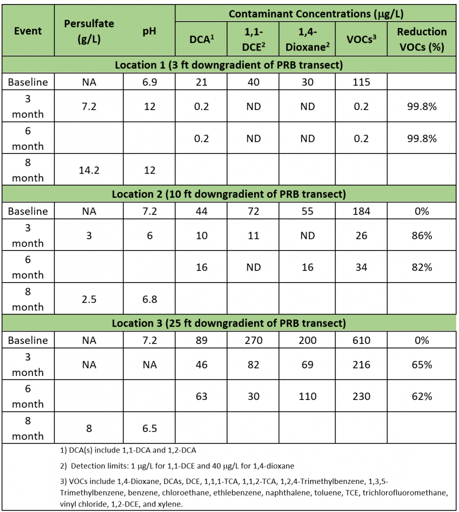
Table CS7-2 lists the monitoring results. These data show that all contaminants of concern were successfully treated at the PRB (to within 3 ft of the PRB) with 99.8% reduction of all contaminants and treatment of 1,4-dioxane to nondetect. The data also showed residual persulfate and alkaline conditions up to 8 months after the pilot-test application within the PRB. This indicates that the geochemical conditions for alkaline-activated persulfate were maintained at the PRB for longer than the designed 6-month time frame. Downgradient from the PRB, low levels of persulfate were observed, indicating migration of the residual persulfate. However, elevated pH was not observed at either of the downgradient monitoring locations, indicating that the persulfate was alkaline activated within the PRB, but those conditions quickly diminished outside of the PRB transect. Despite the loss of alkaline conditions, the contaminants of concern were reduced by over 80% at the monitoring location 10 ft downgradient and by over 60% at the monitoring location 25 feet downgradient. The DCA reductions indicate that much of this treatment is expected to have occurred at the PRB, with the remediated groundwater likely having contamination repartition of contaminated downgradient soils back into the groundwater by the time it was monitored.
Table CS7-1. Column bench-scale test results
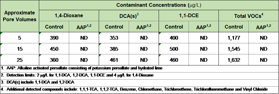
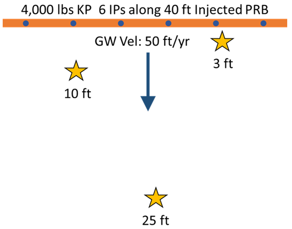
Figure CS7-1. Pilot-test area.
Courtesy of AECOM.
Notes: Monitoring well locations are starred.
ft: feet; ft/yr: feet per year; GW: groundwater; IP: injection point; PRB: permeable reactive barrier; Vel: velocity.
Table CS7- 2. Pilot-test results
LESSONS LEARNED
The laboratory and field applications of ISCO with persulfate were considered to be successful. The column test illustrated the sustained destruction of the contaminants over multiple time points and that the potassium persulfate persisted as designed, based on the mass expected to dissolve and react with the contaminants as the groundwater migrated through the column. The pilot-test performance was also successful. Issues associated with solid-slurry emplacement were observed during the field application. This included the solids settling out in the rods if the injection ceased without the slurry being vacated by a water flush. Potassium persulfate by itself settles much faster than the potassium persulfate with the hydrated lime blended together. Also, increasing the solids concentration of the slurry up to 40–50% (w/w with water) was observed to slow the settling and enhance the handling characteristics. The pilot field application demonstrated successful treatment of the contaminants at the PRB and that the potassium persulfate persisted longer than the 6-month design window.
REFERENCES
Smith, Brant, Brianna Desjardins, Ravi Srirangam, and Dustin Bytautas. 2019. “Treating 1,4-Dioxane with Activated Potassium Persulfate.” Presented at 35th Annual International Conference on Soils, Sediments, Water and Energy. Amherst, MA. October 22, 2019.
Furman, Olha S., Amy L. Teel, and Richard J. Watts. 2010. “Mechanism of Base Activation of Persulfate.” Environmental Science and Technology 44 (16): 6423–6428.
Matzek, Laura W. and Carter, Kimberly E. 2016. “Activated Persulfate for Organic Chemical Degradation: A Review.” Chemosphere 151 (Parales et al.) 178–188.


